Learn common wire harness connector types, key selection factors, and OEM applications to choose the right connector for reliable electrical systems.
Explore how wire harness design withstands harsh environments. Learn key design principles, material choices, and testing methods for lasting performance.

Learn why cable testing standards are essential for OEMs. Explore key requirements, testing methods, and how Kato Cable ensures quality and compliance.
Learn how early supplier partnerships improve wire harness manufacturability, reduce costs, and boost reliability for OEMs with Kato Cable expertise.
Discover how expert wire harness design improves reliability, performance, and lifespan—and how Kato Cable helps OEMs build products that last.
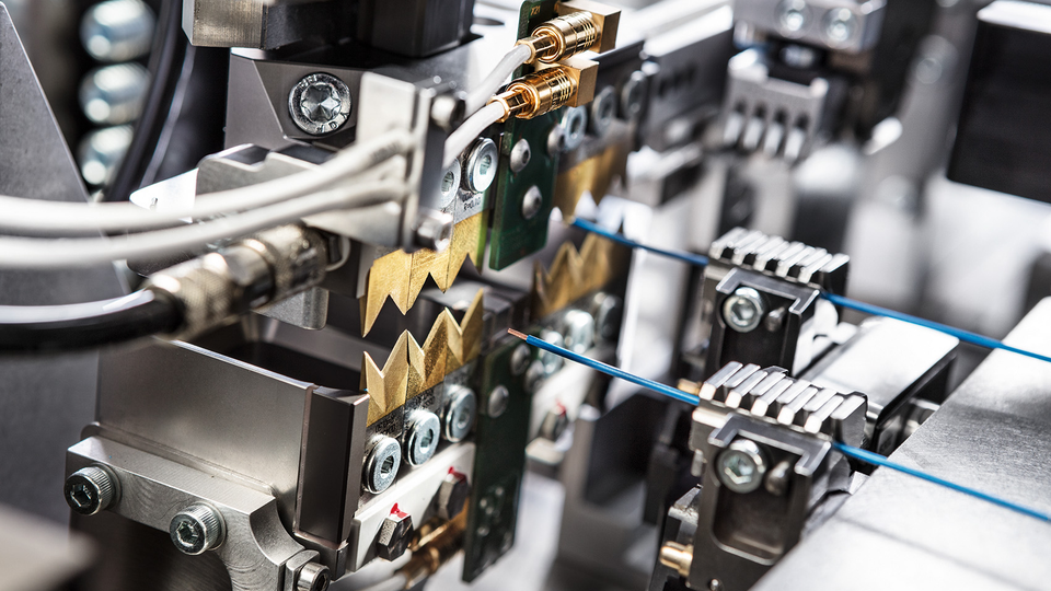
Discover how Kato Cable uses Komax Zeta automation to streamline wire processing, reduce labor, and deliver faster, more precise OEM manufacturing results.
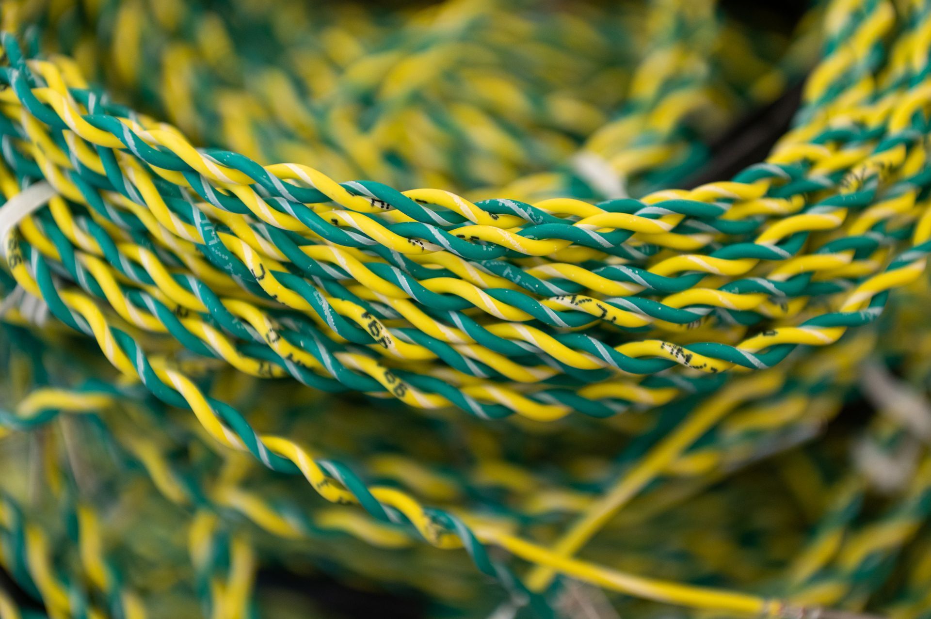
Discover how wire twisting improves electrical reliability, reduces interference, and enhances performance across OEM applications with Kato Cable.
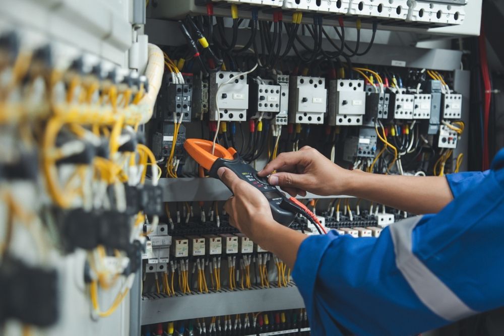
Learn how electrical control panel assembly ensures safe, reliable performance. Explore best practices and solutions from industry experts at Kato Cable.
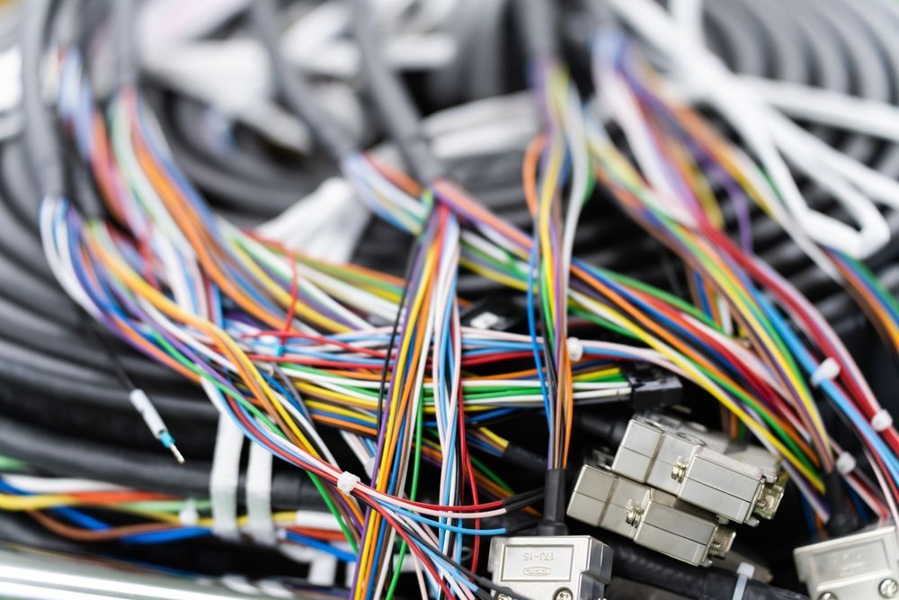
Learn how to troubleshoot cable assemblies and wire harnesses. Discover common issues, proven solutions, and how Kato Cable helps ensure reliability.
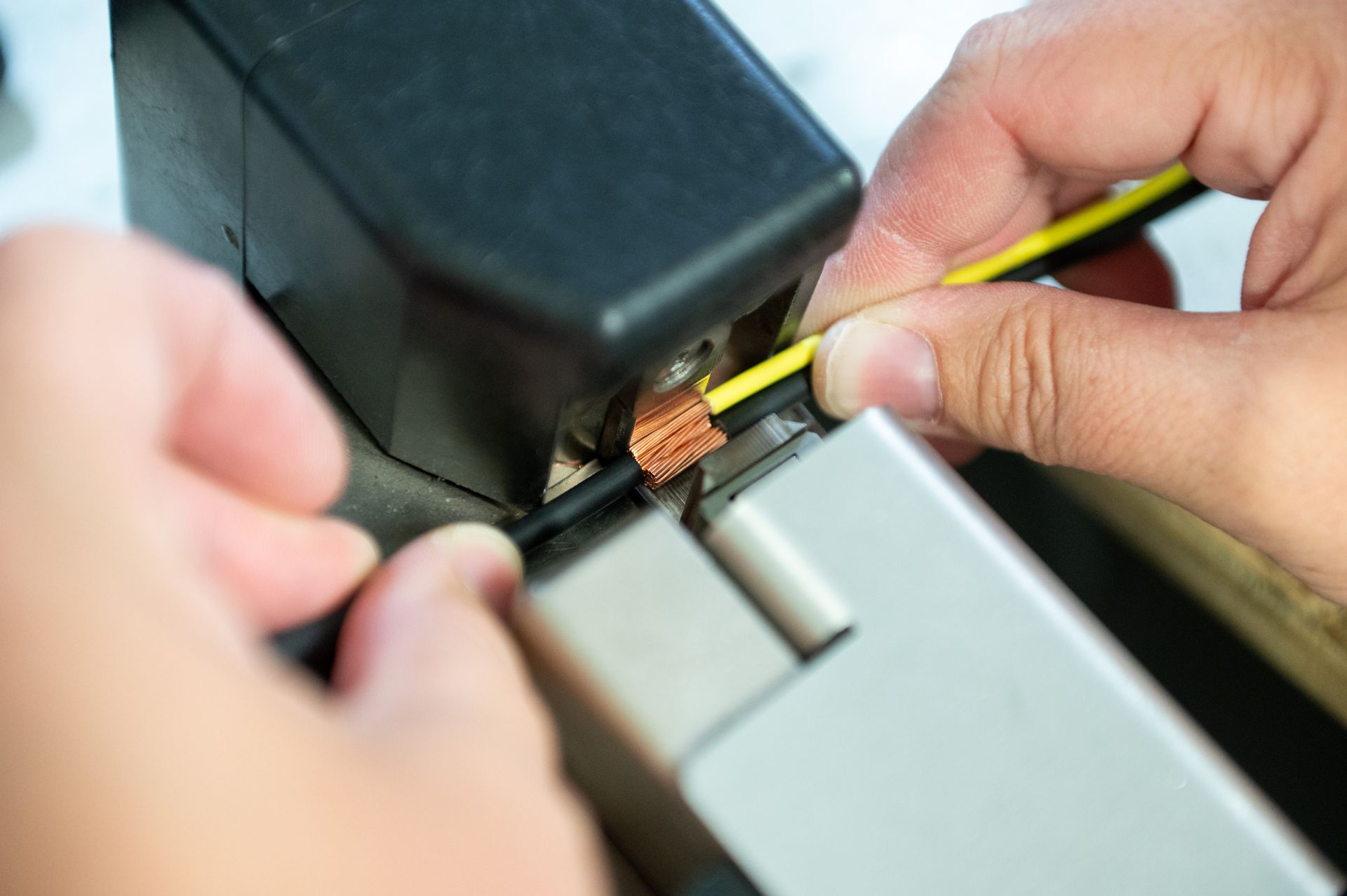
Discover why ultrasonic welding outperforms wire splicing in harness manufacturing—delivering stronger, low-resistance, and scalable connections.