What Is DIN Rail and How Is It Used in Control Panels?
Share Article:
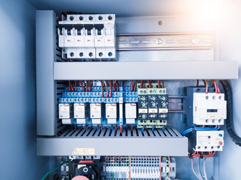
DIN rail is a standardized metal strip that mounts inside an electrical enclosure and holds a control panel’s components. The most common version is 35 mm wide. Circuit breakers, relays, terminal blocks, and power supplies clip onto it instead of being screwed directly to the back panel. That speeds up assembly and makes parts easier to replace later.
The rail’s dimensions are defined under IEC/EN 60715, so components from different manufacturers fit the same rail. Rails still vary in depth, material, and profile, and those choices affect how a panel holds up in service.
How DIN Rail Supports Components Inside a Control Panel
The rail is screwed to the panel’s backplate, usually at intervals of around 6 inches (150 mm). Panel builders often tighten that spacing for heavy devices, vertical rails, or equipment that vibrates.
Each rail-mounted component has a clip on its back. The top of the clip hooks over one lip of the rail, and a spring latch snaps over the other. Removing a part takes a flat screwdriver to pull the latch down.
Because components mount to the rail and not the backplate, a builder can add, move, or replace devices on the same rail, with no new holes needed. End stops at each end of a row keep parts from sliding.
Which Electrical Components Can Be Rail-Mounted?
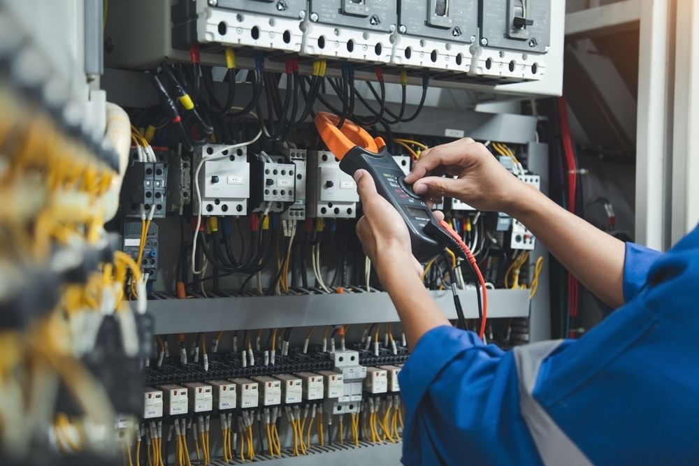
Most of the small devices in a control panel are built for DIN rail. Common examples include:
- Terminal blocks and fuse holders
- Miniature circuit breakers
- Relays, timers, and small contactors
- Power supplies
- PLCs and I/O modules
- Surge protectors
- Enclosure heaters, thermostats, and hygrostats
Larger, heavier parts are a different story. Transformers, big contactors, and drives usually mount straight to the backplate. On equipment that vibrates, even a mid-size power supply can cause trouble. A rail carrying a heavy device can flex and amplify vibration instead of absorbing it. In those cases, a screw-mounted bracket or chassis plate holds up better.
Choosing the Right Rail for Your Control Panel
Most rails look alike at a glance, but profile, depth, and material vary. The right combination depends on what the rail carries and where the equipment ends up.
35 mm Top-Hat vs. Miniature and G-Profile Rails
The 35 mm top-hat rail (TS35) is the default for most industrial panels. It comes in 7.5 mm and 15 mm depths. The deeper 15 mm version resists flexing, so components are less likely to pop off when a technician tightens terminal screws.
Miniature 15 mm rail (TS15) fits small relays and terminals in tight enclosures. G-profile rail, an older asymmetric design, still appears in legacy equipment and some heavier terminal blocks. For new designs, start with TS35 and switch only when a component calls for another profile.
Component Compatibility, Material, and Mounting Load
Check each component’s datasheet for the rail profile and depth it accepts. Steel rail is the stronger choice and grips component clips firmly. Aluminum weighs less and resists corrosion, though it can flex under heavy loads. For wet, salty, or chemical environments, including marine equipment, stainless steel holds up best. Slotted rail is easier to cut and fasten, while solid rail adds rigidity.
Heavy rows of power supplies or contactors need tighter fastener spacing, often around 3 inches (75 mm). They also need screw-on end stops that won’t let go under vibration.

How Rail Placement Affects Wiring and Service Access
A layout can fit every component on the rail and still be hard to work on. Leave about 1.5 to 2 inches between each rail and the nearest wire duct. That gap lets wires bend cleanly and gives a technician room for fingers and tools.
Group rails by function. Keeping power components on one rail and control or signal devices on another simplifies routing and reduces electrical noise. Terminal blocks for field wiring belong near the cable entry, where installers can reach them easily.
Mount rails horizontally when possible, since vertical rails need strong end stops to keep parts from sliding down. Leave roughly 15% of the rail open, too. OEMs often add options in later model years, and spare room avoids a panel redesign.
Illustrative DIN Rail Layout in a Generator Control Panel
The example below shows one common way to organize rails in a standby generator panel. Actual layouts depend on the controller, the enclosure size, and the OEM’s specifications.
Top rail: Circuit breakers, fuse holders, and surge protection for incoming power.- Second rail: 24 VDC power supplies. Mounting them high lets their heat rise away from the relays and controls below.
- Middle rail: Relays, timers, and I/O modules that connect the generator controller to the engine and transfer switch.
- Bottom rail: Field terminal blocks near a bottom cable entry, grouped into AC power, DC control, and sensor circuits like oil pressure and coolant temperature. An enclosure heater and hygrostat sit at the far end, where warm air can rise through the panel.
Generators vibrate and often sit outdoors, so this layout would use 15 mm steel rail, fasteners about every 3 inches, and screw-on end stops on every row. Heavier parts like a battery charger or control transformer would mount directly to the backplate. The heater and hygrostat help keep condensation from forming during winter standby.
How Kato Cable Builds Custom Panel and Rail Assemblies
Kato Cable manufactures wire harnesses, cable assemblies, and control panels for OEMs in the automotive, aerospace, electronics, and industrial equipment markets. Its products go into generators, fire trucks, boats, and other equipment where electrical connections have to hold up in tough conditions.
Sourcing harnesses and panels from one supplier gives OEMs a practical advantage. Terminal rows, duct routes, and harness breakouts can be planned together, so connectors land where the rail layout expects them. Kato Cable partners with each customer to match rail, hardware, and component choices to real operating conditions, from vibration to cold-weather standby.
Request a Quote for Your Custom Control Panel Assembly
Kato Cable builds custom control panels and DIN rail assemblies to OEM specifications. Send your drawings, bill of materials, or
project requirements, and our team can review rail selection, component layout, and harness
integration before production begins.
Request a quote to start the conversation, and follow Kato Cable on LinkedIn and Facebook for updates on wire harnesses, cable assemblies, and control panels.