Main Components of an Industrial Control Panel Explained
Share Article:
Nearly every piece of industrial equipment runs on a control panel. In a generator, conveyor line, pumping system, or agricultural machine, the panel manages how power is delivered, how the equipment responds to changing conditions, and how operators interact with it. When it works as intended, it goes unnoticed. When it doesn’t, the result is nuisance trips, unexpected shutdowns, and hours of troubleshooting in the field.
Performance comes down to the components inside the panel and how they are put together. Most
industrial control panels use the same core families of devices: protection, power conversion, control logic, load switching, operator interface, and safety. Each has a specific role, and each depends on the others and on the wiring that connects them.
For OEMs, understanding these components makes it easier to set clear specifications and get a panel that performs reliably in service.
Main Control Panel Parts and Their Functions
Control panel components work across two connected circuits. The power circuit delivers the energy that runs motors, pumps, heaters, and other equipment loads. The control circuit carries lower-voltage signals that tell those power devices when to start, stop, or change speed. Some components sit between the two, using a small control signal to switch a much larger load. Each device has its own role, and the panel works best when every one is correctly matched to the job it performs.
Disconnect Switches, Circuit Breakers, and Fuses
The disconnect switch isolates incoming power so technicians can lock it out before service. Circuit breakers and fuses protect individual circuits from overloads and short circuits. Breakers can be reset after a trip. Fuses must be replaced but often limit fault current faster, which helps protect sensitive downstream devices.
These devices also affect the panel’s
short-circuit current rating (SCCR), the maximum fault current it can safely withstand. It’s a common misconception that the main breaker’s interrupting rating sets the SCCR. The lowest-rated component in the power circuit sets it. One under-rated device can limit where the equipment can be installed.
Transformers, Power Supplies, and Distribution Blocks
Control power transformers step incoming line voltage down to a level suitable for control circuits. DC power supplies then convert AC power to the steady low-voltage DC that PLCs, sensors, and many control devices need. Sizing both with headroom for future loads helps prevent voltage drops and nuisance faults as equipment changes.
Distribution blocks split a single incoming feed into multiple branch circuits. This keeps connections organized and avoids stacking several conductors on one terminal. Because they sit in the power circuit, their ratings matter. A distribution block without an adequate short-circuit rating can quietly become the device that limits the panel’s SCCR.
PLCs, I/O Modules, and Communication Devices
The programmable logic controller (PLC) runs the panel’s control logic. It reads incoming signals, executes its program, and sends commands to the devices that operate the equipment. I/O modules connect the PLC to the field. Input modules receive signals from sensors, switches, and pushbuttons. Output modules drive relays, contactors, valves, and indicators. Communication devices, such as Ethernet switches and network modules, link the PLC to HMIs, drives, remote I/O, and plant systems.
These are often the longest-lead items in a panel. Confirming availability early and approving alternates in the bill of materials helps
keep production on schedule when a specified model is hard to source.
Relays and Contactors
Relays and contactors both use a small control signal to open or close a separate circuit, but they serve different loads. Control relays switch low-current signals. They often act as interposing devices between a PLC output and a field device, or provide extra contacts for interlocking logic. Contactors are built for heavier power loads such as motors, heaters, and lighting. They have larger contacts designed to handle the arcing that comes with frequent switching.
Matching each device to its load is critical. A relay used where a contactor belongs can wear out quickly. A coil voltage that doesn’t match the control circuit can cause chattering or failure to pull in.
Motor Starters and Variable Frequency Drives
A motor starter pairs a contactor with an overload relay. The contactor switches the motor on and off. The overload relay protects it from sustained overcurrent that can overheat its windings. Starters suit motors that run at a fixed speed.
A variable frequency drive (VFD) controls motor speed by adjusting the frequency and voltage it supplies. It also ramps motors up gradually, reducing mechanical stress and inrush current. That flexibility affects panel design. VFDs generate heat that the enclosure must dissipate, and they can introduce electrical noise. Separating drive wiring from low-level control signals helps keep sensors and communications reliable.
HMIs, Pushbuttons, and Status Indicators
Operator devices are the panel’s interface with the people running the equipment. A human-machine interface (HMI) is a touchscreen or display that shows process data, alarms, and settings, and lets operators adjust parameters without changing the PLC program. Pushbuttons, selector switches, and pilot lights handle simpler tasks: starting and stopping equipment, selecting modes, and showing status at a glance.
These devices are usually mounted through the enclosure door. Their environmental rating should match the enclosure’s, so the panel stays sealed against dust and moisture. On equipment exposed to extreme cold, display performance is worth confirming, since some screens respond slowly at low temperatures.
Safety Relays and Emergency Stop Circuits
Safety relays monitor devices that protect people, such as emergency stop buttons, guard door switches, and light curtains. Standard relays can fail without warning. Safety relays use redundant, self-checking circuits that detect faults like welded contacts or a broken wire, and they prevent the equipment from restarting until the problem is cleared.
An emergency stop circuit uses these devices to remove power from hazardous motion when an operator presses the E-stop. The required level of safety performance depends on the machine’s risk assessment and the applicable machinery safety standards. Those requirements belong in the electrical drawings before the panel is built, so the safety circuit can be wired and verified to the design.
Terminal Blocks, Enclosures, and Mounting Hardware
Terminal blocks are the organized connection points between the panel and field devices. Specialty versions provide grounding, fusing, or a disconnect point for testing. Spring-clamp terminals hold steady pressure under vibration, reducing the loosening that screw terminals can experience.
The enclosure protects internal components from dust, moisture, and impact, and its NEMA rating should match the actual operating environment. Fans or air conditioners remove heat. Anti-condensation heaters keep internal temperatures above the dew point. Heaters aren’t only for cold climates, since daily temperature swings can cause condensation almost anywhere.
A backplate, DIN rail, and wire duct hold components in place and keep wiring organized. Spare backplate space makes future modifications easier.
How Power and Control Signals Move Through the Panel
Power and control signals follow separate paths through the panel. Keeping those paths physically organized makes the panel easier to build, inspect, and troubleshoot.
Power Distribution to Equipment Loads
Incoming power enters through the disconnect, then passes through the main protective device to distribution blocks or a power bus. From there, each branch circuit has its own breaker or fuses, followed by the contactor, starter, or drive that switches the load. Power conductors then exit through terminal blocks to motors, pumps, and heaters. A smaller branch feeds the control transformer or power supply that runs the control circuit.
Sensor Inputs and Controller Outputs
Control signals travel in a loop. Sensors, switches, and pushbuttons send signals through terminal blocks to the PLC’s input modules. The PLC evaluates those inputs against its program. It then energizes outputs that drive relays, contactor coils, valves, and indicators. Routing these low-level signals away from power and drive wiring helps keep electrical noise from causing false readings.
Key Differences Between Common Control Panel Devices
Several panel devices perform similar functions, and confusing them can cause premature wear or compliance issues.
| Comparison | Key Difference |
|---|---|
| Relay vs. contactor | Relays switch low-current control signals; contactors switch high-current loads like motors and heaters. |
| Contactor vs. motor starter | Contactors switch power only; motor starters combine a contactor with an overload relay to protect the motor. |
| Motor starter vs. VFD | Starters run motors at full speed; VFDs vary speed and ramp motors gradually. |
| Circuit breaker vs. fuse | Breakers reset after a trip; fuses are replaced but can limit fault current faster. |
| Standard relay vs. safety relay | Safety relays use redundant, self-monitoring circuits for E-stops and guarding. |

How OEM Equipment Affects Component Selection
The same component can perform very differently depending on the equipment it serves.
Operating environment: Agricultural, construction, and power generation equipment often face vibration, temperature extremes, dust, and moisture. These conditions shape enclosure ratings, climate control, terminal types, and component temperature ratings.
Duty cycle: Frequent starts, high inrush currents, and inductive loads wear devices faster, so components must be rated for the actual duty.
Installation requirements:
Available fault current at the installation site sets the required SCCR. End markets or customer specifications may also require
specific certifications or approved brands.
Serviceability and supply:
Readily available components reduce downtime for end users. Approved alternates for hard-to-source parts protect production schedules.
How Wiring and Harnesses Support Panel Reliability
Wiring is usually the most labor-intensive part of a panel build and the most common source of errors. A correctly specified component can still fail its job if the connection to it is poorly made.
Wire Routing, Identification, and Terminations
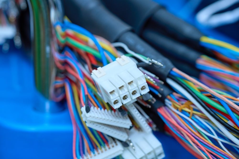
Wires should run through ducts in clean, consistent paths, with enough bending space at terminals to avoid stressing conductors. Clear, durable wire identification that matches the drawings lets technicians verify connections during inspection and trace circuits in the field. Terminations need the correct ferrule or terminal and proper crimp quality, because loose or poorly crimped connections cause intermittent faults that are hard to diagnose.
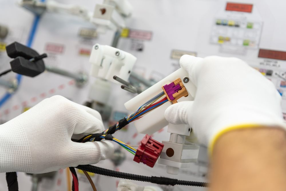
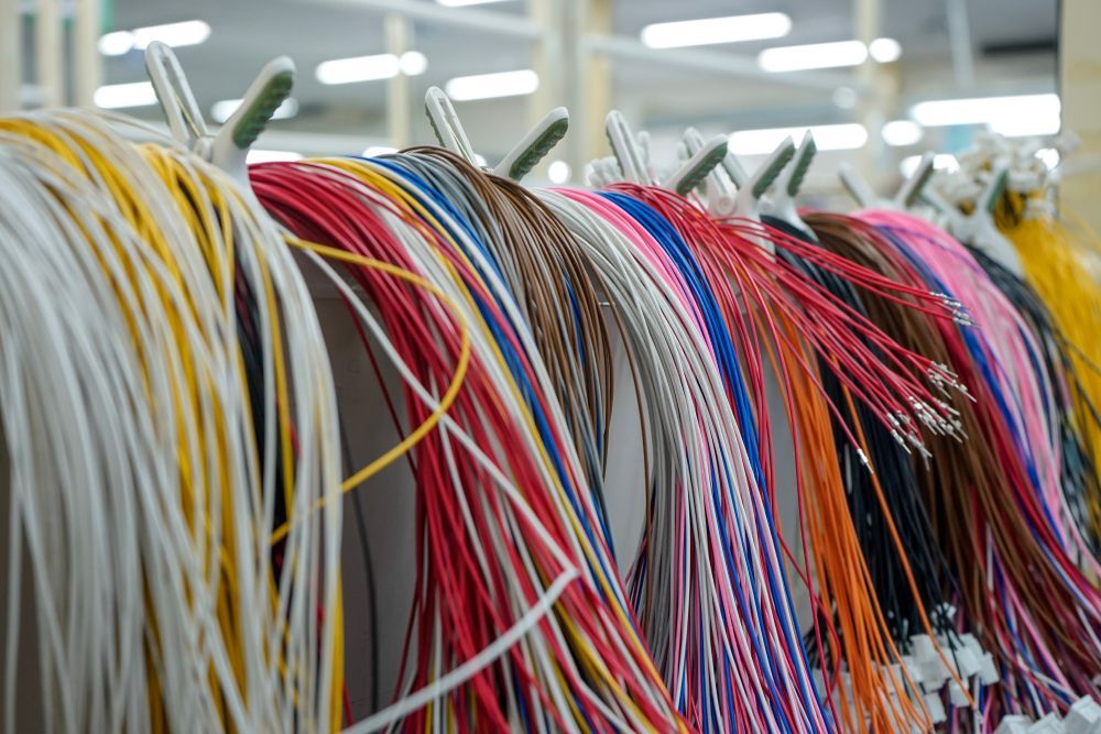
Pre-built wire harnesses can improve consistency here. Cutting, marking, and terminating wires before panel assembly reduces wiring time and errors, especially on repeat builds.
Grounding, Strain Relief, and Service Access
A solid grounding and bonding scheme protects personnel and reduces electrical noise. Strain relief at cable entry points keeps vibration and pulling forces off terminations, which matters on mobile and outdoor equipment. Organized, labeled wiring with access around components also makes future maintenance faster and safer.
Component and Assembly Requirements to Verify
Confirming key requirements before production prevents most rework and startup delays.
Voltage, Current, and Short-Circuit Ratings
Every component should be rated for the voltage and current it will carry, including inrush and continuous load. Device ratings in the power circuit should support the panel’s required SCCR, and the final rating should be marked on the nameplate. Substitutions deserve the same check, since a lower-rated replacement can lower the SCCR of the entire panel.
Drawings, Bills of Materials, and Approved Parts
Current electrical drawings, wiring diagrams, and a complete bill of materials give the build team a single reference. Confirming revision levels before production keeps outdated information off the floor. Listing approved alternates for long-lead or hard-to-source components lets the build continue without unplanned redesigns. Labeling standards and testing expectations should also be defined before assembly begins.
Request a Quote for Build-to-Spec Control Panels
Kato Cable builds industrial control panels to OEM specifications from customer drawings, bills of materials, and wiring diagrams. With wire harness and control panel assembly under one roof, Kato brings the same attention to terminations, routing, and identification to every connection inside the enclosure, and every panel is inspected against specifications before shipment.
Ready to discuss your next project?
Request a quote from us.